Simple Switch Wiring ARB Dual Air Compressor
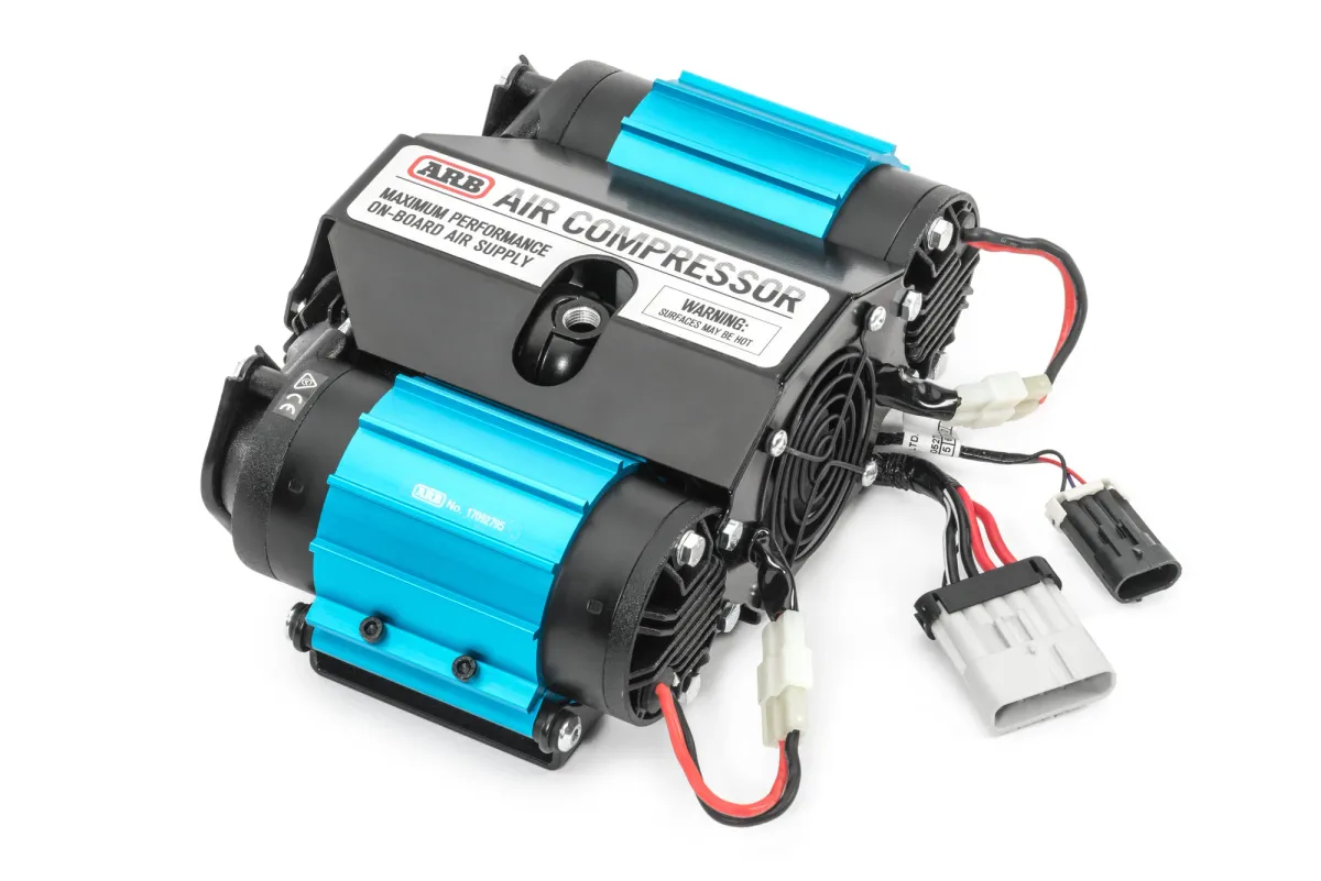
When you buy the ARB dual air compressor it comes with a wiring harness suited for dual air lockers using a master switch. Great for the limited market who run dual air lockers, not the best all-round wiring for those who want a simple on / off air compressor for tyres and general use.
The ARB dual compressor comes with an in-built relay, making it easy to wire. All you have to do is switch the one coil wire, the rest are for switches that have back-lighting. Hook-up the power to your switch and one switch wire. That’s it.
The default wiring harness must be hacked, one way or another, the best thing you can do is lessen the nonsense wiring in your vehicle. Don’t try and leave all the connectors in place if you have no intention to ever use air lockers. Also, the diodes are still needed. Obviously if you plan on installing air lockers in the future, then hack it carefully with everything intact so you can easily correct when air lockers go in.
Important: Diodes are a one-way device allowing electricity flow one way only. They’re installed for the compressor to stop leakage back through your system when the motor starts. They must be installed in the correct direction, otherwise power will not flow.
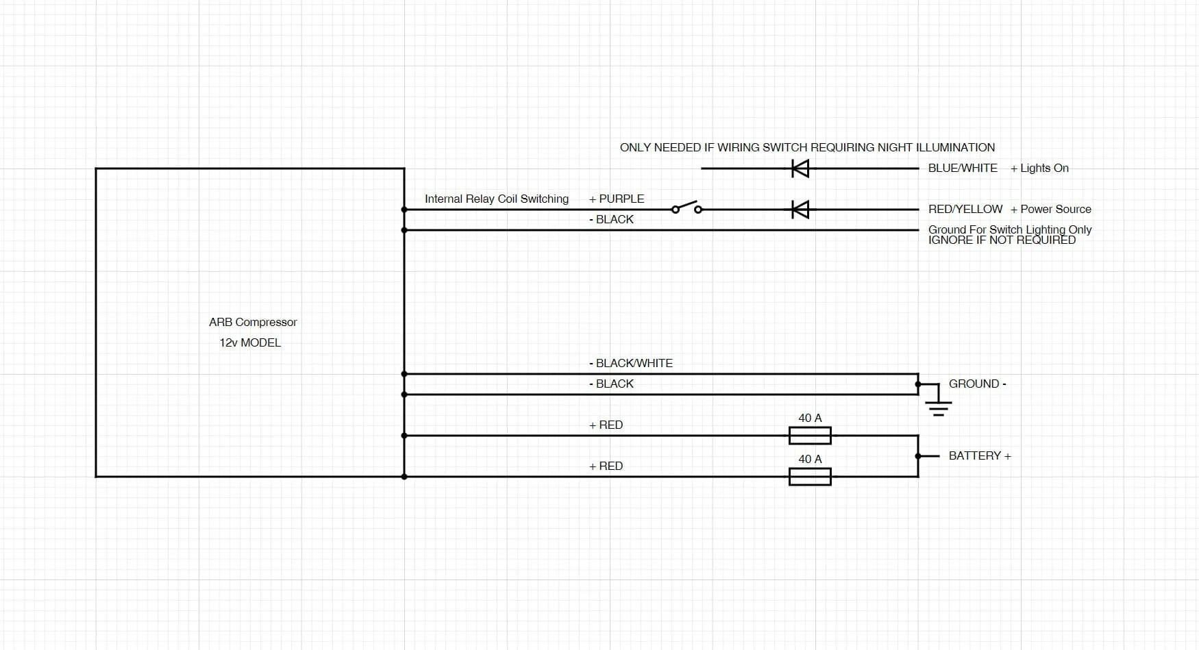
Hot Tip: Parallel wiring and fuses are legal and acceptable, however, if you can I would recommend a single 80amp fuse. Ensure you cut the positive wires to the same length, its important with parallel wiring that the wires are the same length, thus the same resistance. This is not required for the ground wires, as they serve a different purpose than the parallel positives, however, if you cut the ground wires back you will find two joined into one, and for the two, the same rule applies if you go that far. The positive and negative do not need be the same length, just parallel wires of one type so they both distribute the current equally.
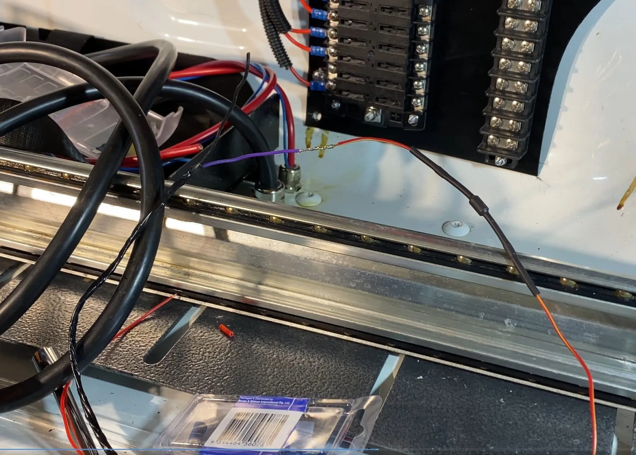
You can see above, the diode is cut from the harness, the compressor switch wire is cut away, the two soldered together, ensuring the diode remains the correct way flowing electricity towards the plug.
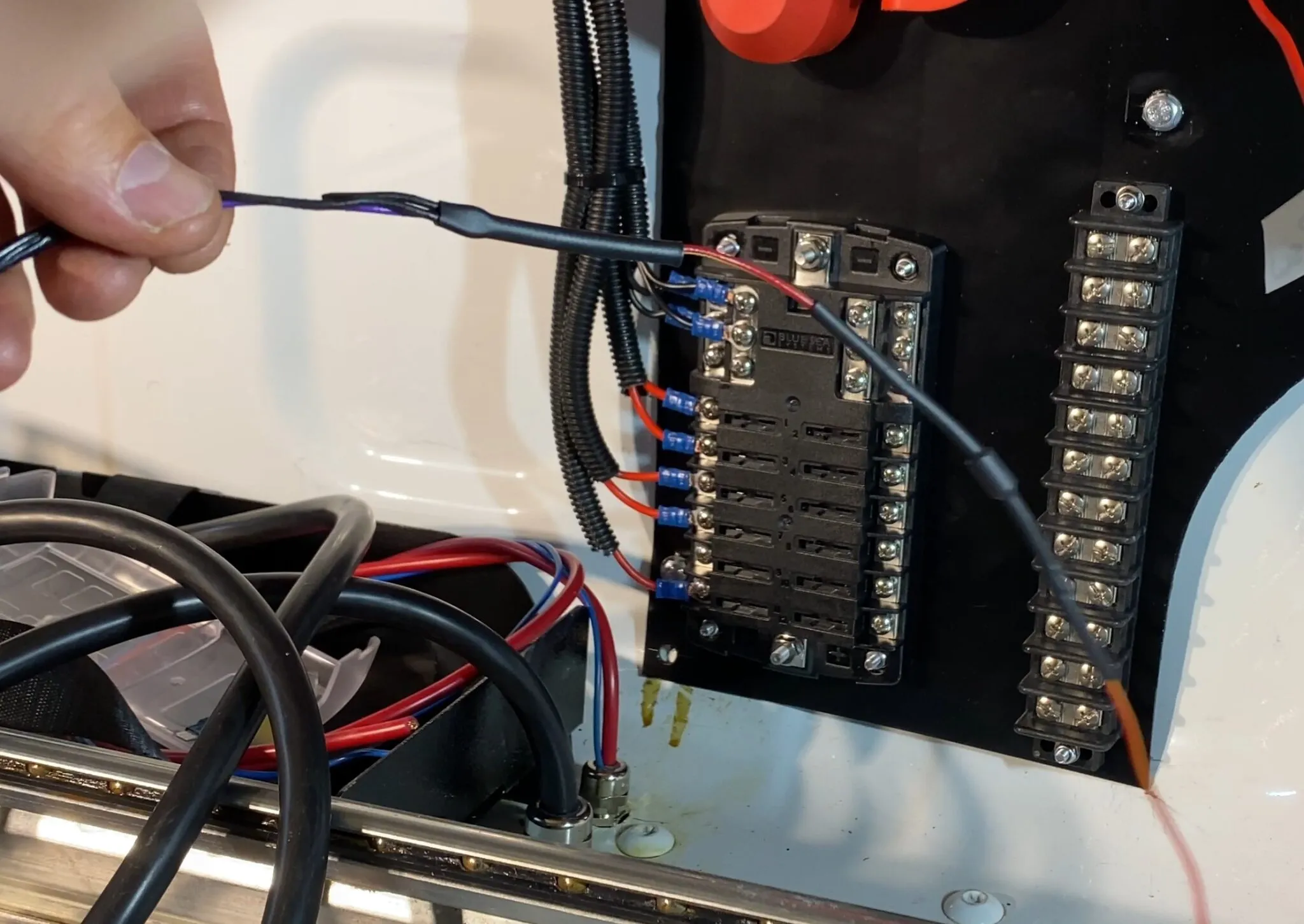
Completed, the black wire is folded over and unused for switching where you don’t require switch lighting.
To give an example using my Dmax, I have my switches in the cabin, pictured below. I run from my power source, into the cabin switch, out of the cabin switch through the diode to the compressor purple wire. Push switch and power flows to turn on ARB in-built relay.
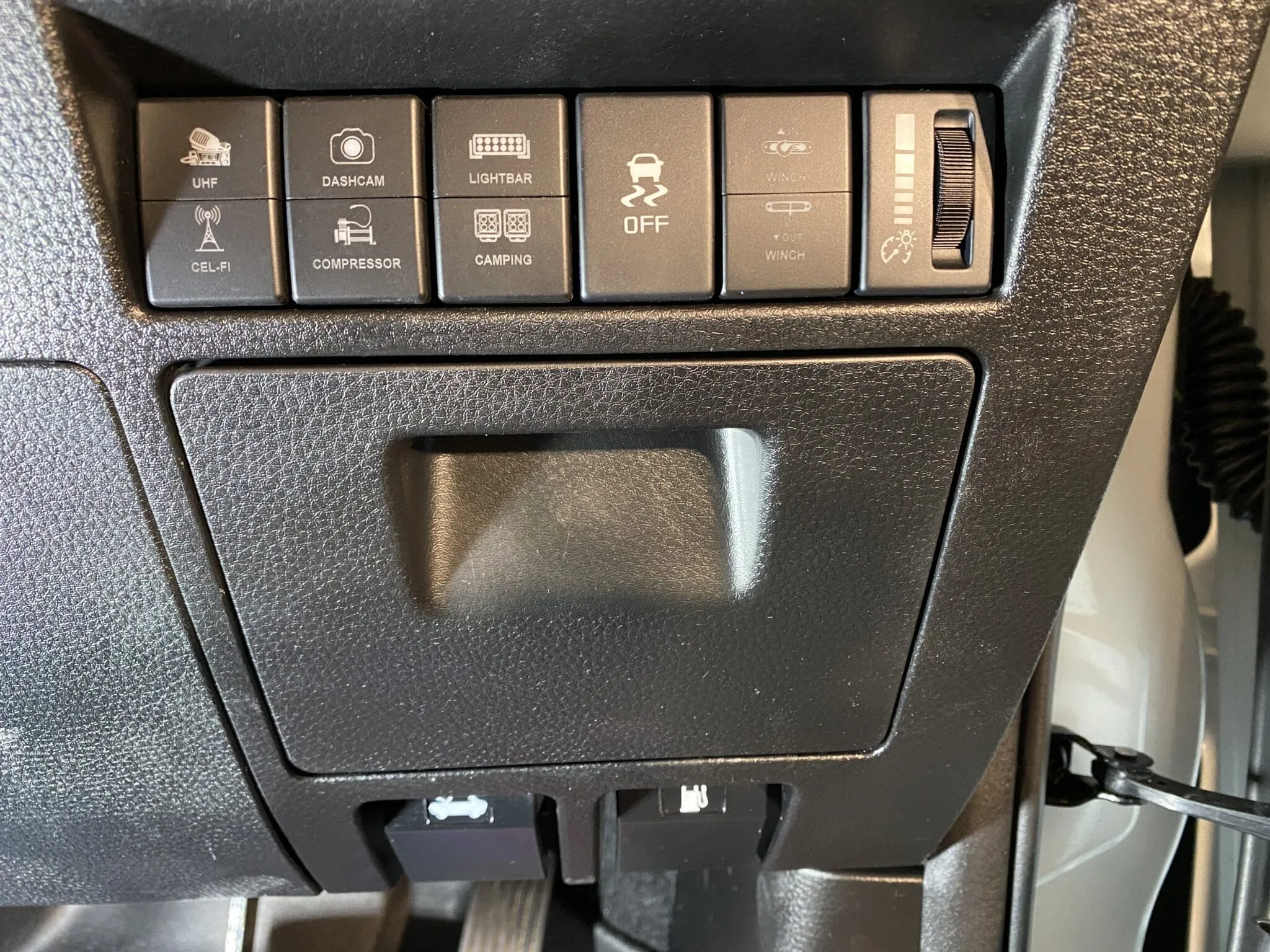
My switch panel has lighting, but uses wiring from the opposite switches, rendering the ground and lighting wire void in the ARB harness.